Working in the pre Computer Age of the 1950s
It was early one Friday evening in 1967 when I took my children to the works, up the stairs and entered the computer room where they gazed in wonder at the lights flashing and machines whirring, reminiscent of the Tardis with which Doctor Who had begun to grace our living rooms.
My colleagues who were adept at Fortran 4 programming had loaded the design problem into the IBM1130 and would collect the printed result on the Monday morning. This heralded the start of a new age.
But my story had begun twelve years before where at Kings, the great Professor Coulson had led me to a first and to a lifelong love of chemical engineering theory and practice.
In the 1950s chemical engineers had received a good grounding in unit processes, fluid flow, heat exchange, mass transfer and other related topics.
Practical application of these in design as always relied on the acquiring and use of data. Without an Internet, handbooks such as Perry and for specific areas, books such as Matheison's gases and also company records were the source of data.
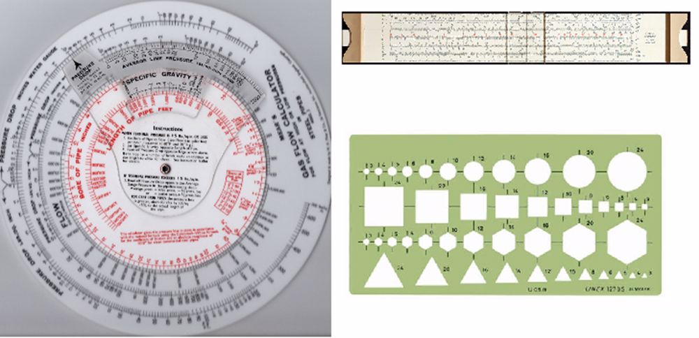
Everything was in pencil and paper with the engineer's key piece of equipment - the slide rule. Most of these were the linear type with trigonometric and loglog functions, some were pocket sized and others were cylindrical. As the slide rule was concerned only with the numerical value the engineer became very adept at fixing the decimal point mentally. Specialist calculators such as the rotary gas flow calculators calibrated for length and diameter of pipe, fluid type, flow and pressure drop were particularly useful.
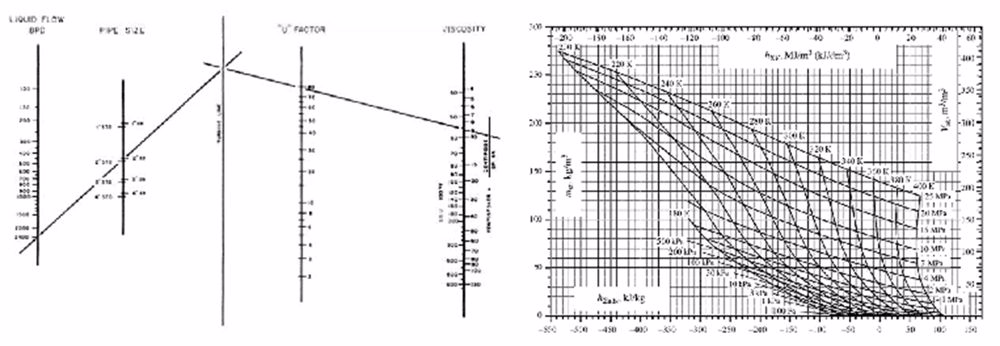
When starting on a design the nomogram was an essential tool to give a rapid solution to many complex problems though with limited accuracy. This however was not critical as the accuracy of the solution would also be in the selection of what physical coefficients (e.g., heat and mass transfer coefficients) applied to a particular case.
Where greater accuracy of calculation was required, tables such as log tables were used. Manual calculators (basically adding machines) came into common use, and in the 60's electronic desk calculators were starting to appear.
Once the basic design was worked out and roughed out on paper, the flowsheets (showing how the basic process and equipment is connected) and the P&I diagrams ( which showed the instrumentation and control) had to be developed. These were written out on paper, stencils providing neat and quick ways of depicting symbols and shapes.
Moving on to the actual design and equipment, specifications would vary with the company. In the case illustrated the flow diagram of the process is cross referenced to the data sheet for each item of equipment, which summarised the design and from which the mechanical and electrical design could proceed.
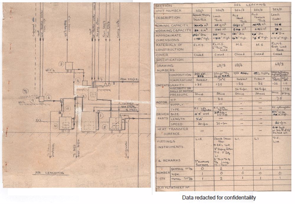
The chemical engineer would examine the subsequent mechanical drawings to ensure these were in accordance with the process design specification.
For certain types of plant, modelling was a good way of optimising layout. These models could be readily dismantled and rearranged until the ideal solution was reached and could then be used in the final preparation of plant drawings. For plant such as cryogenic air separation plant where the cryogenic section was concealed inside a 'cold box' an accurate model was very useful in investigating problems while the plant was running. Such models however were expensive.
Once drawings were complete, checked and authorised. they were transferred to the tracers where they were carefully traced and printed out as blueprints for use by equipment manufacturers, plant construction, site erection, training, operating manuals and plant records.
Where appropriate, analogue simulators were used for the training of operators as every aspect of control other than very simple parameters such as level, flow, pressure, temperature relied on human judgement.
This would continue until the advent of computer control of plant and even then human intervention was a consideration.
The IBM 1130 computer at which my young children had gazed in awe had a 1 megabyte disk drive that stored the operating system, compilers and object programs, and program source generated and maintained on punched cards and tape.
A generation later the son of the little girl who wondered at this spectacular equipment is developing cutting edge designs of electric vehicles for a 'green' world using software programmes on a one million times larger 1TB hard drive and 32Gb RAM.
His NX Nastram programme uses boundary conditions (forces, pressures, temperatures, heat convection, fluid flow, material properties, etc) to generate the optimum design.
From this, 3D printing gives the final image and can even be used for casting tools. In this way he can create a low cost mass produced product with the minimum material, sometimes combining many pieces into one to save on assembly costs.
His second piece of software called A-Priori deals with the manufacturing process optimising, the manufacturing process both physical and financial.
While this is mainly mechanical engineering similar programmes can raise plant design to its full potential.
However for the older generations memories of the pre-computer age remain and whatever the mechanism either manual or computerised the eventual success rests with human understanding of the chemical engineering, on ability and on judgement.